Blog Archives
How to Draw Shear Diagrams
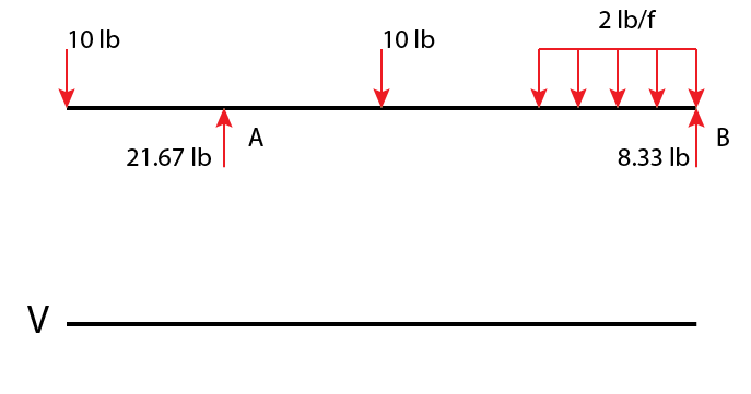
Shear diagrams are an easy way to visualize shear values along a beam or member and also reveal the maximum positive and negative shear values.
The first step will always be to simplify any and all load distributions into point loads and to solve for all exterior reactions.
Begin the shear diagram by drawing a horizontal line, this is the line for zero shear. I like to draw my shear diagrams directly below the actual member so that they line up and I designate my shear diagrams with a big V.
Closed Conduit Hydraulics – Darcy-Weisbach Equation
The Darcy-Weisbach equation is used to determine flow characteristics in closed conduit systems (pipes). It is probably more common than the Hazen-Williams equation due to it being able to solve for systems in both laminar AND turbulent flow.
$$ h_f = f \frac{L}{D} \frac{V^2}{2g} $$
- headloss \(h_f\) (ft)
- friction factor \(f\), length \(L\)
- length \(L\) (ft)
- diameter \(D\) (ft)
- velocity \(V\) $$\frac{ft}{s}\)
- gravity g \(32.2 \frac{ft}{s^2}\)
Friction Factor
The friction factor \(f$$ is either given or must be calculated using a Moody-Stanton diagram (available in both the AIO and CERM). Getting the friction factor from a Moody-Stanton chart requires the Reynolds Number \(Re\), and relative roughness \(\frac{\epsilon}{D}\). Click here to continue reading
How to Solve for Reactions
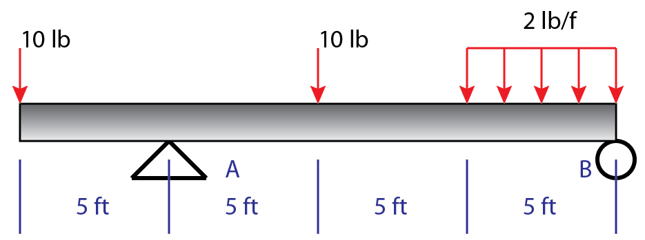
The first step in many problems is solving for reactions, here is an example of some situations that you may encounter.
Simplify the distributed load into a point load:
$$ \frac{2lb}{ft} *5ft = 10 lb $$
Since this distribution is constant the load is applied at the midpoint, 2.5 ft to the left of B. (If the distributed load was not linear the point load should be applied at wherever the “center of mass” of the distributed load is; the center of mass of a constant distributed load is the midpoint). Click here to continue reading
Zero-Force Members
Zero force members are members in a truss/frame that theoretically have no force in them. Being able to identify these members swiftly will aid you on the PE Exam and in life in general (possibly).
There are two rules to look for when identifying zero-force members.
- Joints with three members where two of the members are parallel, and there is no external load. The third member will be zero-force.

- Joins with two members and no external load. Both members are zero force.
 Click here to continue reading


