Shear and Bending Stresses in Beams
Beams are one of the main design elements a structural engineer will work with. This is a loaded simply supported beam:
For the PE exam, a loaded beam has two main options for failure, shear and bending.
Shear Stress
Shear stress is caused by forces acting perpendicular to the beam. Shear forces are visible in both cross sections and profiles.
The formula for average shear at a spot on a beam is:
$$ \tau_{avg} = \frac{F}{A} $$
F is the force applied (from the shear diagram or by inspection)
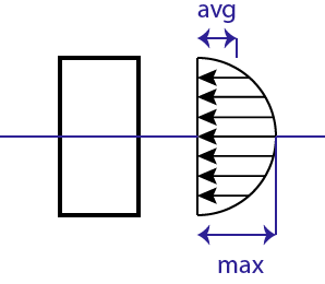
A is the cross-sectional area of the beam. When looking at the shear load dispersed throughout a cross-section the load is highest at the middle and tapers off to the top and bottom.
The formula for max shear in a few different shapes is:
$$ \text{Rectangle } \tau_{max} = \frac{3F}{2A} $$
$$ \text{Circle } \tau_{max} = \frac{4F}{3A} $$
$$ \text{I-Beam } \tau_{max} = \frac{F}{A_{web}} $$
For I-Beams the shear is generally only considered in the web of the beam. The web is the long vertical part. These ares are all listed in the Steel Manual and may also be in some other more general test references. Remember to use the maximum shear force (found from a shear diagram or by inspection) when finding the maximum shear.
The maximum shear in the simply supported beam pictured above will occur at either of the reactions.
Bending Stress (Stress from Moments)
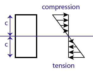
Loads on a beam result in moments which result in bending stress. Loaded simply supported beams (beams supported at both ends like at the top of the article) are in compression along the top of the member and in tension along the bottom, they bend in a “smile” shape. Here is a cross section at an arbitrary spot in a simply supported beam:
Loaded Cantilever beams (beams mounted on one end and free on the other) are in tension along the top and compression along the bottom. These would bend downward in a “half frown”. For these the picture above would be upside down (tension on top etc). Each beam and loading configuration is different, and even segments differ within the same beam!
The formula to determine bending stress in a beam is:
$$ \sigma_b = \frac{Mc}{I} $$
Where M is the moment at the desired location for analysis (from a moment diagram).
c is the distance from the neutral axis to the outermost section (for symmetric cross sections this is half the overall height but for un-symmetric shapes the neutral axis is not at the midpoint).
I is the Moment of Inertia. For a rectangular beam \( = \frac{bh^3}{12} \). I is also given in tables in the steel manual and other reference materials.
The moment of inertia and c are often combined into a single number representing the physical characteristics of the cross-section, S.
$$ S = \frac{I}{c} $$
Use S like so:
$$ \sigma_m = \frac{M}{S} $$
S is given in many tables and can save a lot of time on the exam. For a rectangular beam \(S = \frac{bh^2}{6} \).
The maximum stress for a beam uses the same formula as above but make sure to use the highest moment in the member, this is found on the moment diagram.
Notes
Bending Stress is higher than Shear stress in most cases. If the member is really short or there is a high load close to a support (cutting the beam like scissors) then the shear force may govern. Watch out for those cases.
Posted in Structural Breadth and tagged beam design, bending moment, bending stress, pe exam, shear stress, structural breadth. Bookmark the permalink. 1 Comment.


Great information, but do you have anything on Signal Design